
The Establishment of Simulation Model of Stretcher bed
A Three - dimensional CAD Model for the Construction of Stretcher bed
Although ADAMS \View itself has its own physical modeling capabilities, but for some complex models can not be accurate and rapid modeling. To this end, this paper uses MSC@ADAMS and CATIA interface software SimDesigner to establish the three-dimensional CAD model of the lathe bed mechanism. SimDesigner is an interface software specially developed by MSC to realize MSC \ ADAMS and CATIA seamless connection. Users can use SimDesigner to model, assemble and add constraints and drivers in CATIA interface. Motion simulation can generate MSC \ ADAMS The Cmd file will be. Cmd file can be imported directly into the ADAMS \View dynamic simulation.
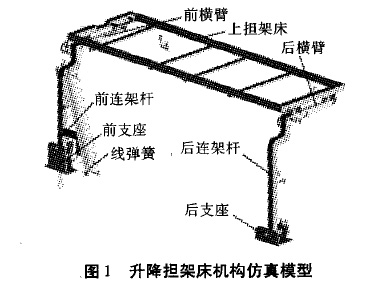
The lower brackets of the new type of ambulance bed are mounted on the floor of the carboard, and the front and rear stand are hinged together with the front and rear bearings respectively. The upper fulcrum of the oil and gas springs is installed on the side wall of the car. The lower fulcrum is installed on the front And rotates together with the front stand bar around the front bearing rotation axis. Because the characteristics of the oil and gas springs are complicated, the oil and gas spring model is simplified and simulated by the linear spring with the stiffness and damping characteristics provided by ADAMS \ View toolbox. The minimum support force and stiffness of the oil and gas spring are respectively Of the preload and linear stiffness simulation. A good simulation model is shown in Figure 1.
Add constraints and drivers
As shown in Figure 1, the front and rear arm and the front and rear seats, as well as the front and rear arms and the upper stretcher bed are bound by the rotation between the front and rear arm and front and rear And the connecting rods are respectively connected by rigid coupling. After defining the quality of each component, convert the model to. Cmd format file, and then import ADAMS \ View. In the ADAMS \ View in the definition of line spring, the fulcrum is set to with the earth fixed (Add to Ground), the lower fulcrum is set to the front with the fixed (Add to Part). Then add a rotary drive to the rotation pair between the front and front bearings, and the drive function expression is set to -ld * time (angular speed constant, 1 ° / s).
Parametric model
ADAMS \ View provides powerful parametric modeling capabilities. In the analysis, only need to change the size of these design variables, the virtual prototype model can be automatically updated. In this paper, the fulcrums and z-axis coordinates of the spring are parameterized respectively. The parameter names are set to DV_spring_ up_X and DV_spring_up_z (hereinafter referred to as x and z) respectively. The spring stiffness and preload are also parameterized, and the parameter names are set separately For DV_stiffness and DV_preload (hereinafter referred to as K and P). Parametric simulation analysis can be performed after setting an initial value and a variation range for each parameter.
 Official WeChat